Product Description
What’s in the box
Beyond Vision’s beRTK® Base Station comes enclosed in a custom-made casing, assembled to ensure the best protection of the device before it reaches you. If you receive the device with any part missing or broken, please contact Beyond Vision immediately.
Inside the case you should find the following components:
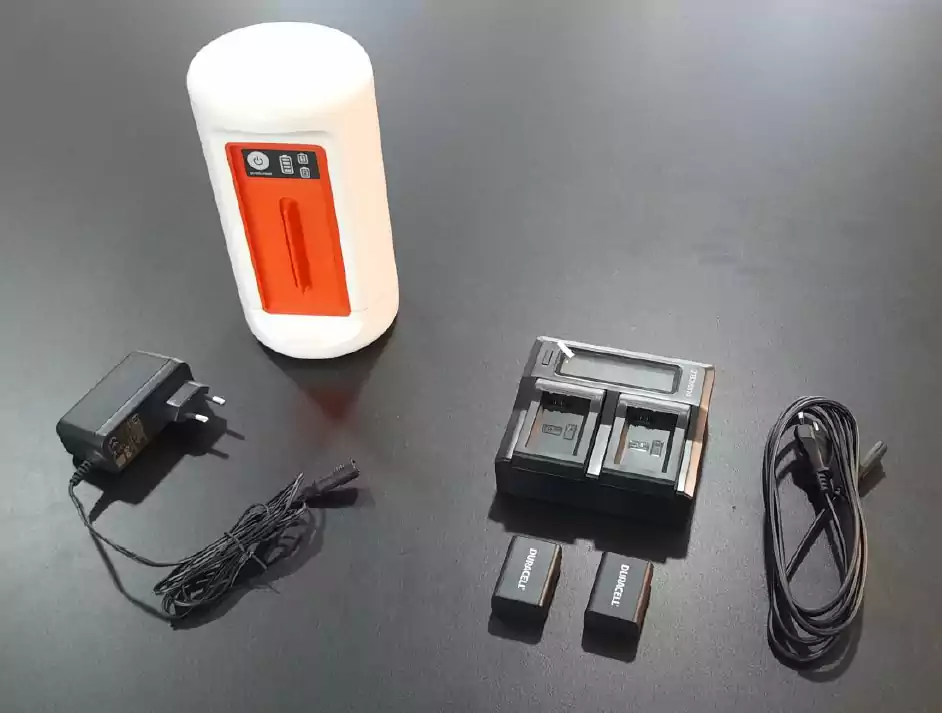
Fig. 89 beRTK® Base Station Kit components
RTK Base Station: the base station itself;
2 Batteries: two Li-Ion encased batteries, prepared to be inserted into the right and left slots of the device;
Battery charger and cable: battery charger for the batteries;
Mains power supply: Transformer that enables the connection of the device to a mains power source, if available;
beRTK® Base Station
The macro block of the RTK Base Station can be seen in the following figure:
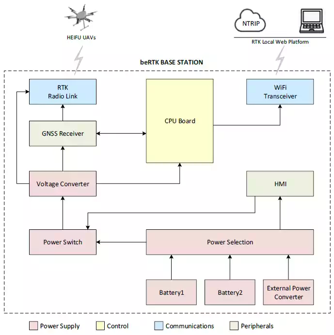
Fig. 90 beRTK® Base Station’s block diagram
Battery1, 2: Li-Ion batteries that are the basis of the device power sources;
External power: enables the connection of an external power source. This power source must deliver a voltage between 7V and 22V and must be capable of delivering at least 15W;
Power selection module: smart power switch module to perform a smooth switch between the external power source and the two batteries;
CPU Board: the device’s “brains”;
HMI: front-panel indicators (battery status and power sources available);
RTK positioning: positioning module, used to accurately determine the base’s geographic position;
RTK Radio Link: radio link used to broadcast the position correction messages;
WiFi Transceiver: WiFi link, used to connect this device to other Base Stations to enable the exchange of data between them.
Physically, the beRTK® looks like the figure below:

Fig. 91 beRTK® main parts
It is mainly composed by: * RTK Base Station: the device’s body; * Front-panel: contains the power switch, as well as the battery status and power sources available; * Battery trays: two battery trays enable hot-swap; * Power-supply connector: contains the power connector;
On the front and back panels of the RTK Base Station, one has access to the connectors and status indicators according to the picture below:
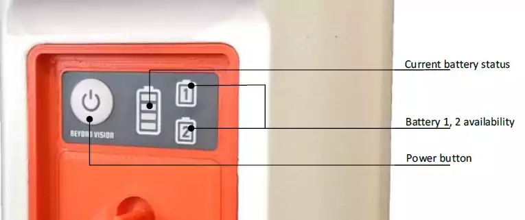
Fig. 92 beRTK® front-panel
In detail:
Power button: switches the RTK Base Station on or off (this is a toggle button). Please press the
button briefly to toggle between on and off. This button has a LED indicator to enable the user to confirm the on/off status of the RTK Base Station; * Battery status indicator: 4 LEDs indicate the battery’s current status. If all LEDs are on, the battery is full or close to full. If no LED is on, the battery may still have some charge; * Power sources available: indication of which power sources are available. * Power connector: located in the back panel, it enables the connection to an external source of power.