Product Description
What’s in the box
Beyond Vision’s HEIFU® comes enclosed in a custom-made special casing, assembled to ensure the best protection of the device before it reaches you. If you receive the drone with any part missing or broken, please contact Beyond Vision immediately.
Inside the case you should find the following components:
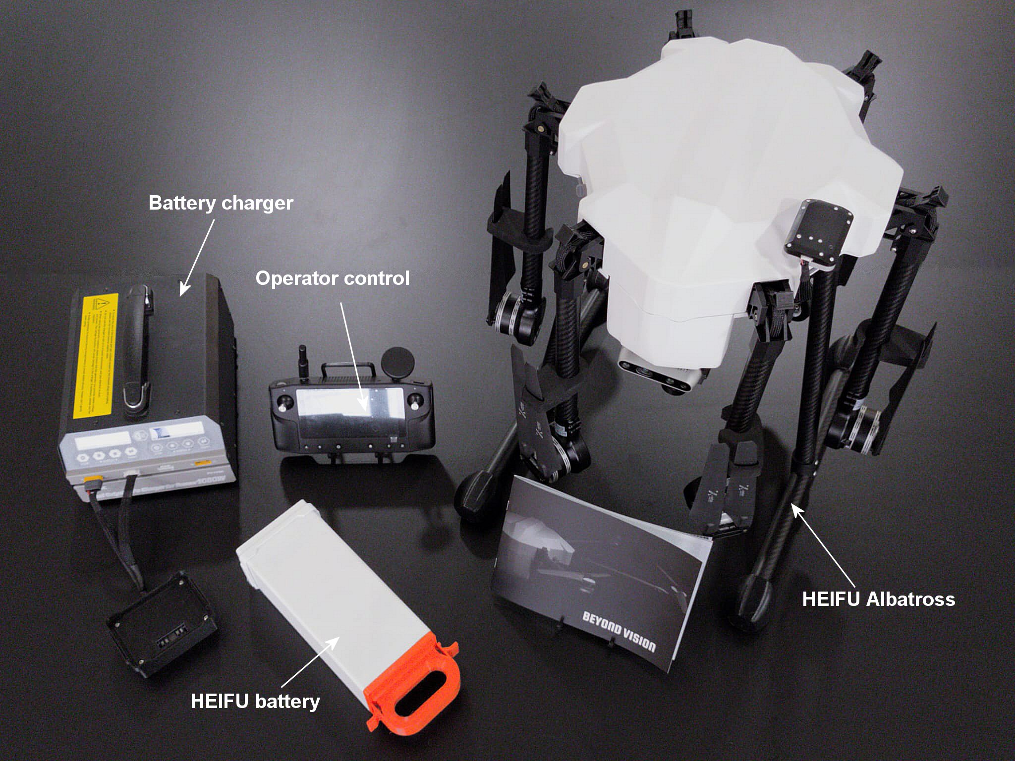
Fig. 3 HEIFU® kit components
**HEIFU® **: the drone itself. Encased with the arms folded, for easier transportation and smaller casing. The propellers are attached to the arms with foam pieces to ensure a safer transportation. Please refer to section HEIFU® for a more detailed description of the parts;
Operator control: the wireless manual drone control. Please refer to section Operator Control for a more detailed description;
HEIFU® battery: high-density, heavy-duty Li-Po battery that powers up the drone;
Battery Charger: main charger and cell balancing station for the Li-Po battery;
If you purchased a beXStream® platform license (one-year access is provided upon drone’s purchase), you will have access to the web application (or desktop app). Please refer to section General risks concerning the usage of flying vehicles for further instructions on how to register and login using your license.
HEIFU®
The HEIFU® is part of an ecosystem that includes the beXStream® platform, local and remote communication networks and accurate positioning systems. The macro block diagram of this ecosystem can be seen in the following figure:
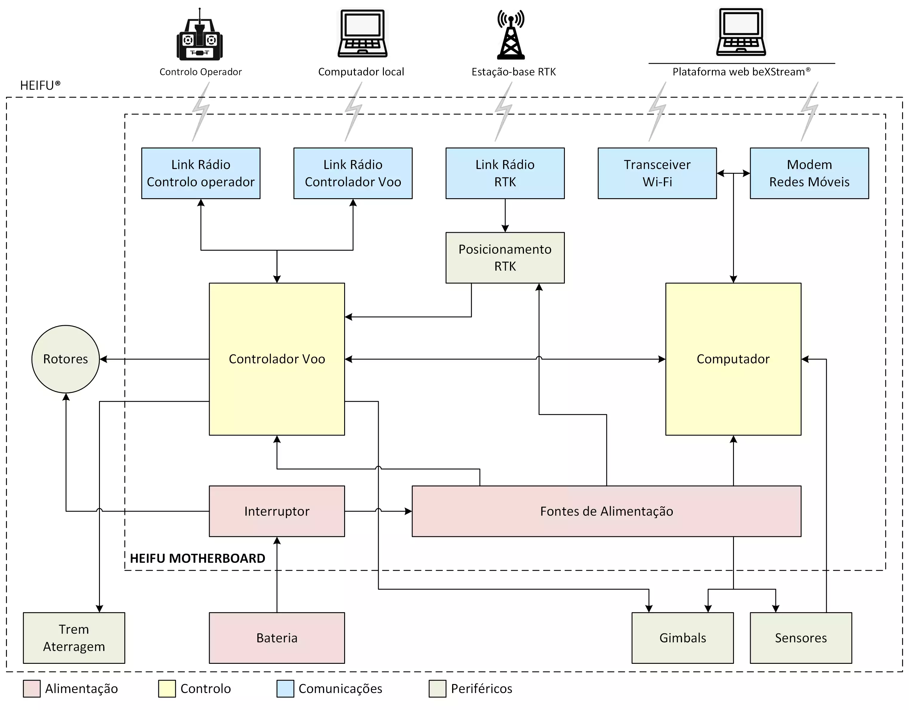
Fig. 4 HEIFU® ecosystem block diagram
Battery: a heavy-duty Li-Po battery that powers the system;
Power Supply: power supply, in charge of generating the needed voltages for the system to work;
CPU Board: the system “brains”, based on a Nvidia Jetson module;
Flight Controller: flight controller module, which controls each of the six drone rotors;
Rotors: the rotors themselves;
GPS RTK: Positioning module, which includes an INS (Inertial Navigation System), so that the drone can know where it is, where it goes and what is its speed, with a high accuracy;
Gimbals: if purchased, the gimbals can be in direct connection with the flight controller;
Sensors: if purchased, the sensors are powered from the drone’s bottom panel and connected to the CPU board via one of the multiple interfaces available;
Operator Control Radio Link: wireless link to the operator control;
RTK Radio Link: wireless link to the RTK base station;
Flight Control Radio Link: if purchased, wireless link to the flight controller (within a certain range, flight information can be retrieved from the flight controller;
Wi-Fi Transceiver: Wi-Fi transceiver module, so that the drone can use the Wi-Fi network (if available) to connect to the system’s web platform;
Mobile Network Modem: mobile network module (4G or 5G), so that the drone can use the network to connect to the system’s web platform;
Physically, the HEIFU® looks like the figure below:
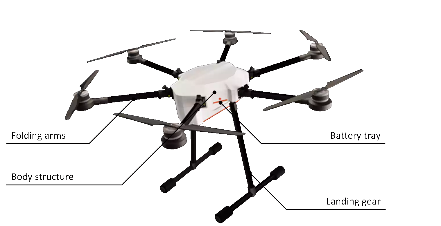
Fig. 5 HEIFU® main parts
It is mainly composed by:
Body structure: where all the electronics are located;
Folding arms: six folding arms which hold the rotors;
Landing gear: used when the drone is not flying;
Battery tray: to shelter the battery and a rail to hold the payload (gimbals, sensors and other customized supports).
On the back side of the drone, one has access to the on/off button, some status indicators and the interface connectors, according to the picture below:
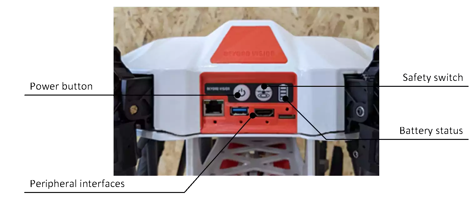
Fig. 6 HEIFU® back connectors and interfaces
In detail:
Power button: switches the drone on or off (this is a toggle button). Please press the button briefly to toggle between on and off. This button has a LED indicator to enable the user to check the drone status;
Safety switch: The safety switch can be used by the local user to enable/disable the drone’s safety mode. When in safety mode, the rotors are disabled ensuring that the drone doesn’t fly and the propellers don’t move, preventing accidents;
Peripheral interfaces: From left to right:
Ethernet Port: enables the user to use an Ethernet connection.
USB Port: enables the user to connect one USB 3.0 device to the drone’s CPU board.
HDMI Interface: enables the user to connect the CPU board to an external display.
SIM card slot: enables the user to insert a SIM card for mobile network access.
Battery status: 4 LEDs indicate the battery current status. If all LEDs are on, the battery is full or almost full. If no LED is on, the battery may still have some charge, but the drone should not fly under any circumstances, as the battery level is already very low.
Operator Control
The Operator Control (also known as RC or Remote Control) allows the operator to control and monitor all aspects of the drone and its operation. This includes piloting, interacting with the attached camera and its gimbal, and building and tracking missions. All while providing the necessary information to ensure a safe and controlled flight, such as drone telemetry, camera’s video feed, environmental information, and more. This can be done with a local drone within the control’s radio link range, or with a drone anywhere in the world, as long as both the drone and the controller have access to the internet. The picture below shows the front view of the Operator Control, which is composed by a touch screen, two joysticks for piloting the drone, a wheel, and six buttons.
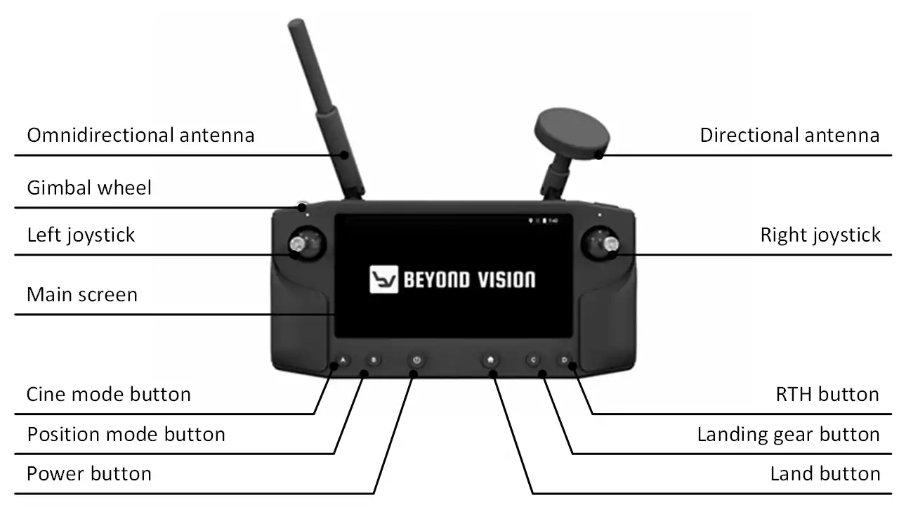
Fig. 7 Operator Control front view
The main interfaces can be described as:
Directional and omnidirectional antennae: Antennae that establish the wireless connection between the Operator Control and the drone;
Left joystick (up/down): Drone’s throttle control;
Left joystick (left/right): Drone’s yaw control;
Right joystick (up/down): Move the drone forwards/backwards;
Right joystick (left/right): Move the drone sideways;
Main screen: Displays information for the user and provides additional actions (see next sections for further details);
Button A: Cine mode;
Button B: Position mode;
Power switch: Switches the device on/off;
Home: Commands the drone to land immediately;
Button C: Open and closes the drone’s landing gear;
Button D: RTL (Return To Land) command;
Gimbal wheel: Controls the primary gimbal’s pitch movement;
When you open the app, you should see the following menu
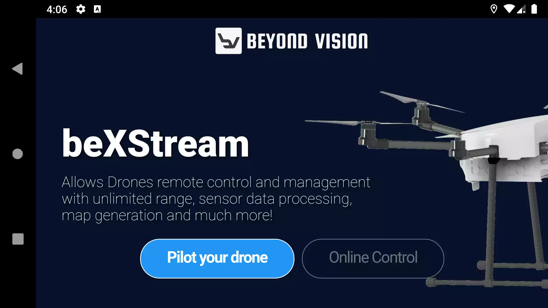
Fig. 8 Operator Control splash screen
Here, the user has two options:
Pilot your drone: meant for local scenarios where you are communicating through radio with a drone close to the controller;
Online Control: reserved for drones that are connected to the internet (not currently active).
In the next paragraphs, these two options will be described.
Pilot your drone
When you select this option, you will see the following screen:
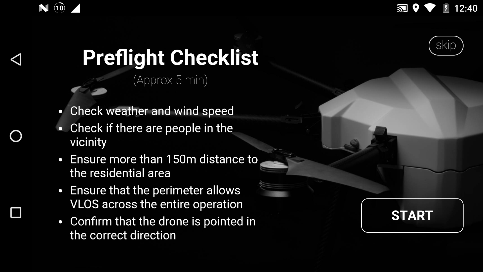
Fig. 9 Pilot your drone, initial screen
At this stage, you can go through the recommended steps of pre-flight verification or simply skip them and enter the monitor screen:
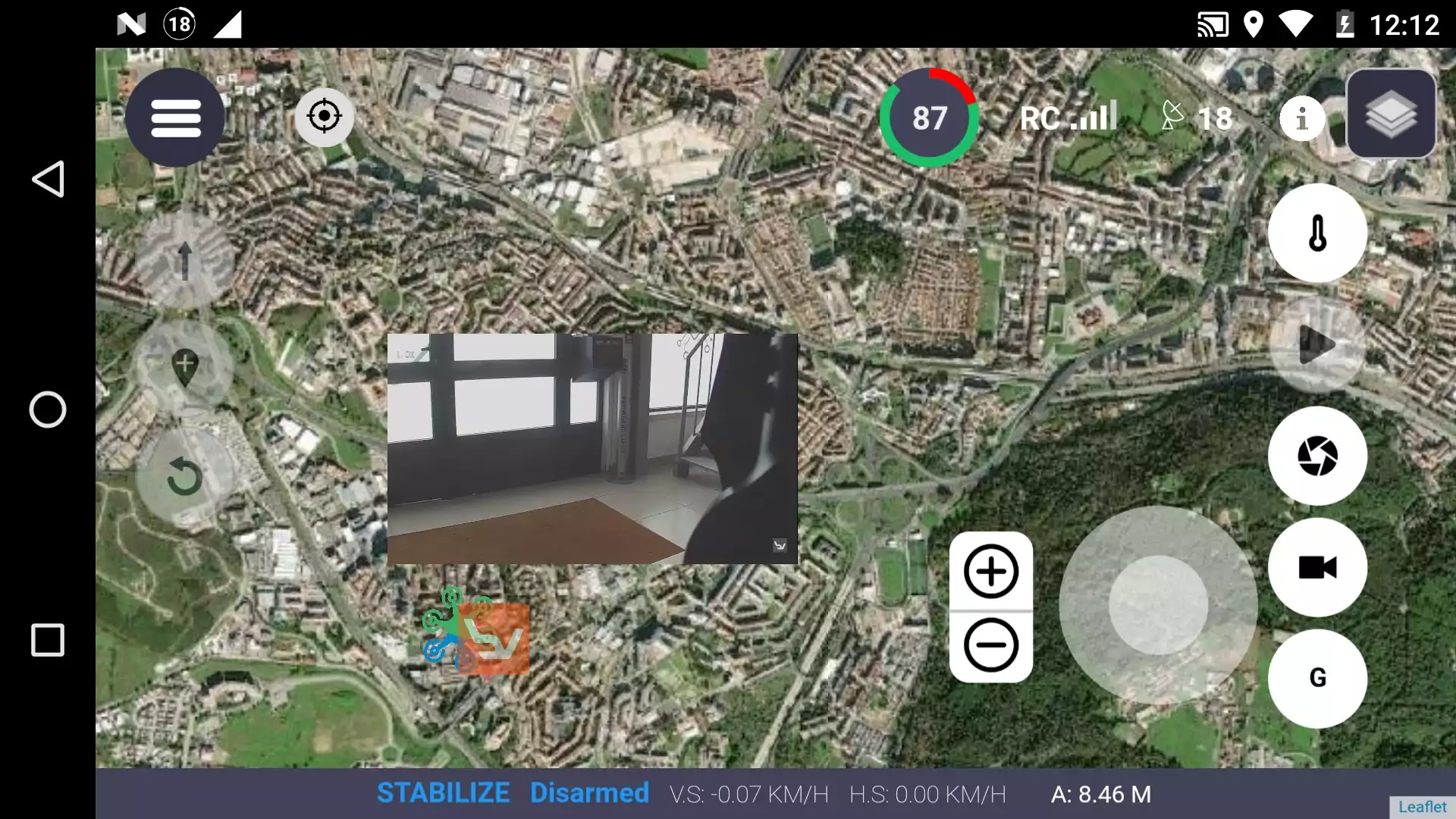
Fig. 10 Pilot your drone, map screen
In the top left bar, the icons allow the user to change between different views:
Drone monitor: this is the default page;
Mission build: create a mission for the drone to follow (see section Drone monitor view);
Drone calibration: perform a drone calibration (see section Mission builder view).
Drone monitor view
In the screen background Fig. 11 you can see a map of the area surrounding the drone and/or the Operator Control. When the drone is outside of the current observed area, you can use the target button (top left) to center the screen on the drone location. The current view of the map is downloaded in real-time form the internet and as such, you will need an internet connection to take the most out of your experience. If you do not have an internet access at the flight location, you can download the maps beforehand and they are stored in the internal memory of the Operator Control:
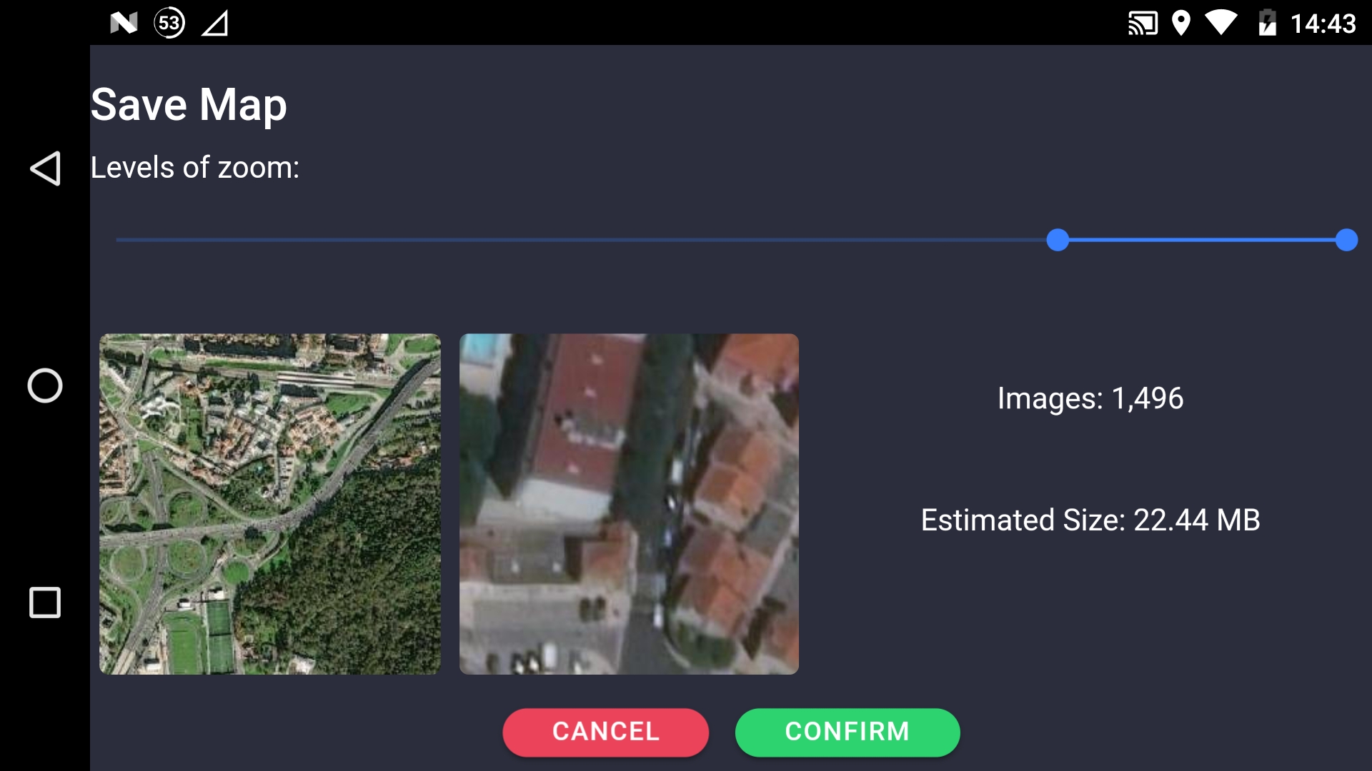
Fig. 11 Pilot your drone, maps download
You can download multiple sections of the map, even if they are not related, to be used whenever the monitor screen is covering that area. Press “Confirm” to download the maps you need. Back to the drone monitor screen, in the top right corner, the screen shows the current system status:
Weather forecast (if an internet connection is available): the icon will show if the forecasted conditions are considered safe to fly or not. You can also click on the icon to see the actual values of the most important parameters to ensure a safe flight:
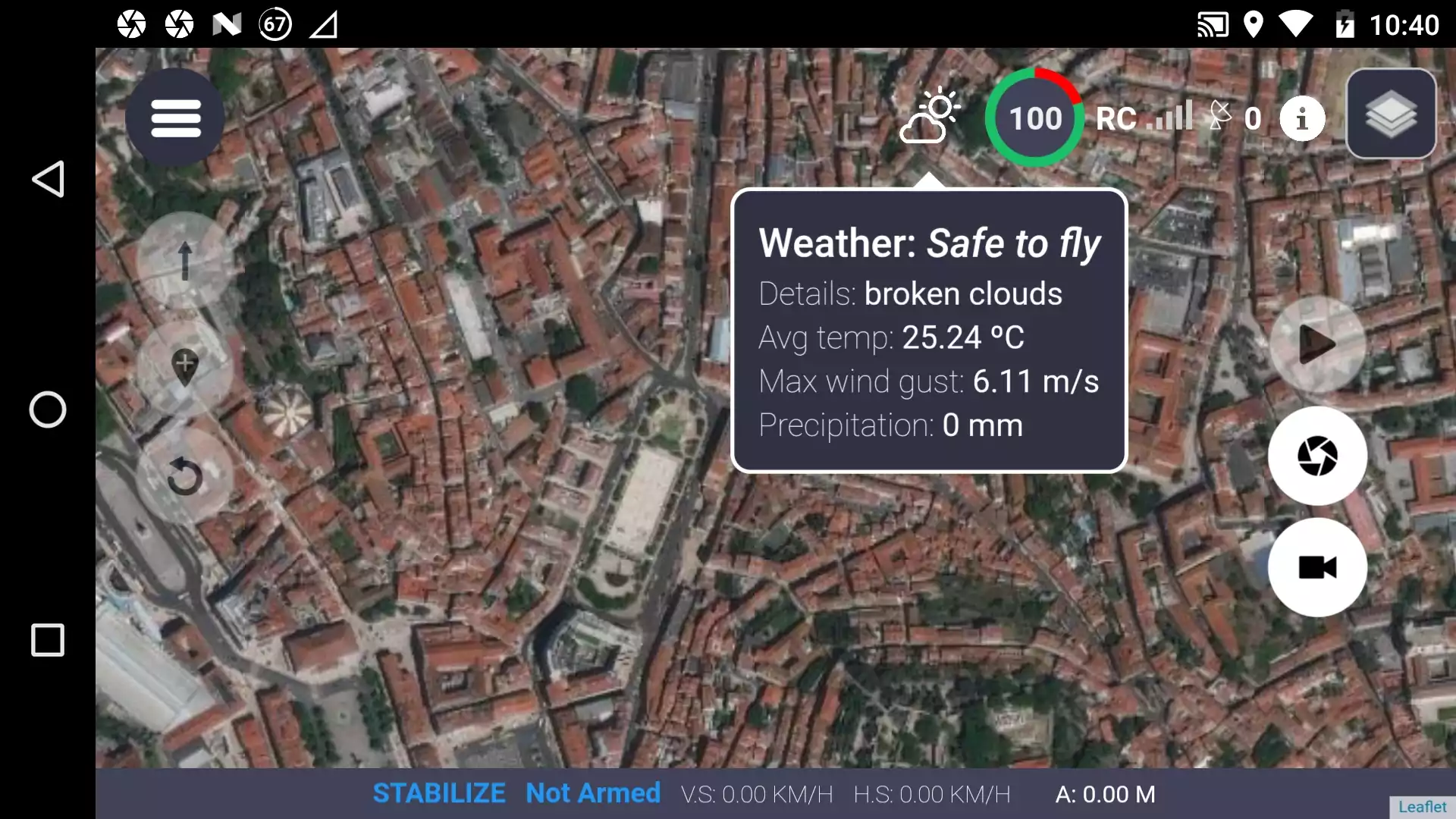
Fig. 12 Weather forecast on the Operator Control
Battery level: as a percentage, with the colored circles indicating if the current level is safe to fly (green) down to critical level (red);
Strength of link connection: shows the strength of the radio signal received from the drone;
Satellites: the number of satellites that the drone for positioning determination. It is advisable to have at least 15 satellites for a good performance;
Additional features: other features such as access to the preflight setup, viewing the messages sent by the drone, and the download of map sections to use while offline;
Map settings: you can change the settings of the map shown in background, as well as search for specific locations.
In the bottom bar one can see:
Flight mode: The current drone’s flight mode;
Drone arm: shows whether the drone is currently armed or not;
Speeds: vertical and horizontal speed of the drone;
Altitude: altitude of the drone.
On the left-hand side, there are three buttons to allow the user to:
Takeoff and Land;
Set waypoints on the map;
RTL (Return To Land) flight mode activation.
On the right-hand side, there are several buttons that allow the user to interact with the currently attached camera:
Video stream source: swap between thermal and RGB camera (if applicable);
Video stream play: starts and stops the video stream of the currently available camera, running in a pop-up that the user can drag around the screen. If the user clicks the pop-up, it turns full-screen. Click again to turn it to just a pop-up once again:

Fig. 13 Video stream as s pop-up
When in full-screen mode, there is an additional button on the left-hand side that can be clicked to view the video stream only (double clicking anywhere on the screen will take you back to the last view):
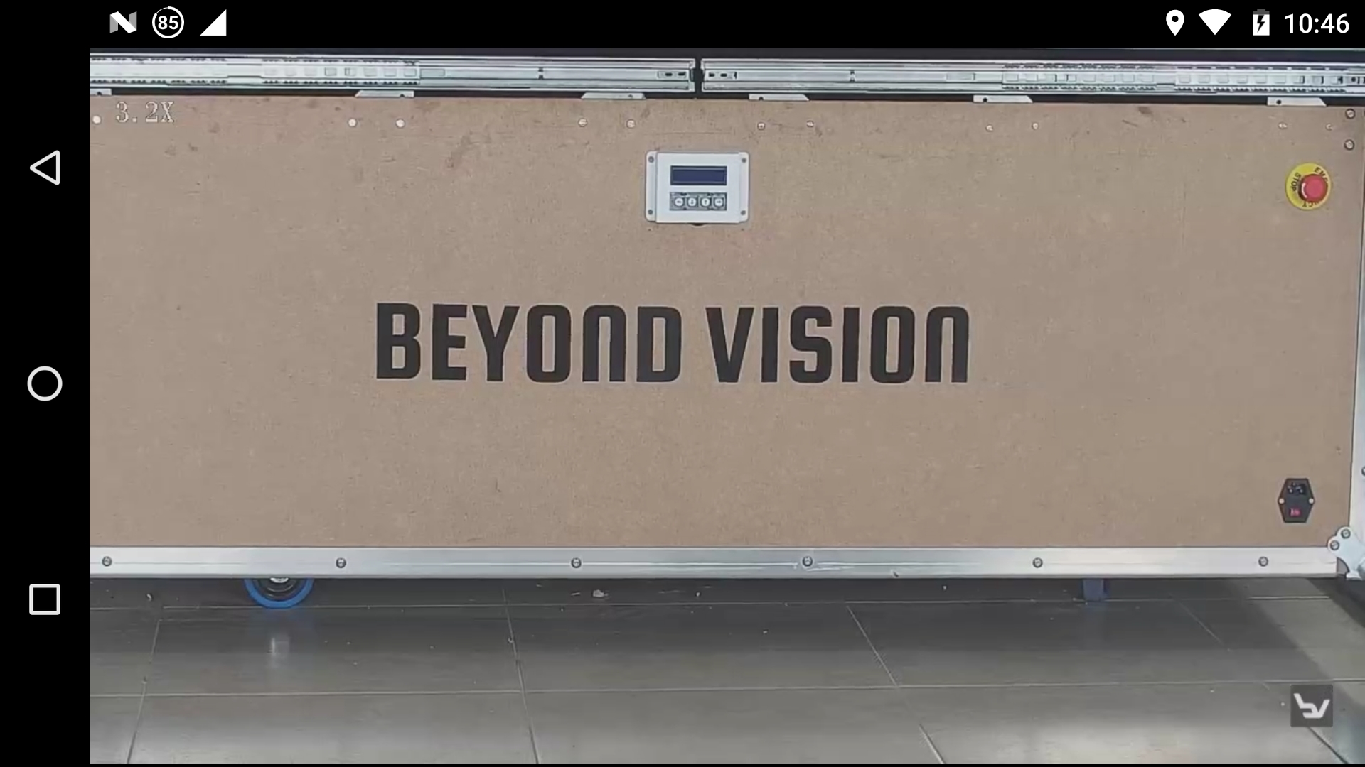
Fig. 14 Video stream only on screen
Snapshot: this button allows the user to take a picture;
Video recording: this button allows the user to start/stop recording the video captured by the drone;
Gimbal: by clicking on this button, the user will be able to see some additional buttons to allow him to control the gimbal:
a thumbstick to control where the gimbal is pointing to;
two buttons to zoom in and out
Mission builder view
If the user selects the mission builder view, the following screen will appear:
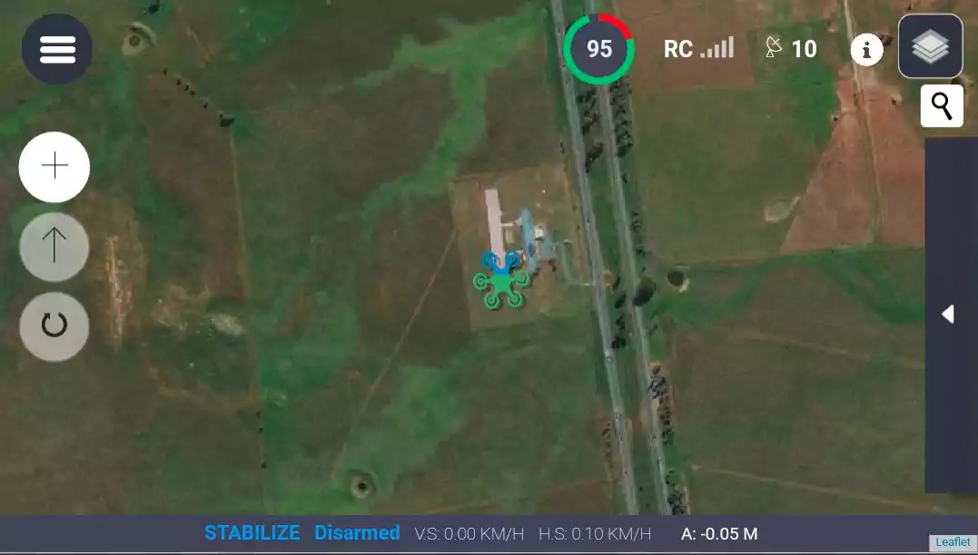
Fig. 15 Mission build screen
In this view you can create, edit, export and import missions. To enable the user to use these functions, the screen will show, on the left-hand side:
Create/import/export mission: this button allows the user to create missions, import or export files containing missions from a file or import a mission directly from the drone;
Download mission: this button allows the user to download a mission to the drone. The drone can be instructed to automatically start the mission afterwards;
Clear current view: this button clears the current view of any missions the user may have created.
On the right-hand side the user has a sliding window to open the Edit Mission menu. In this menu, the user can change a set of settings for the execution of the flight like altitude, flight speed, behavior on each waypoint and others:
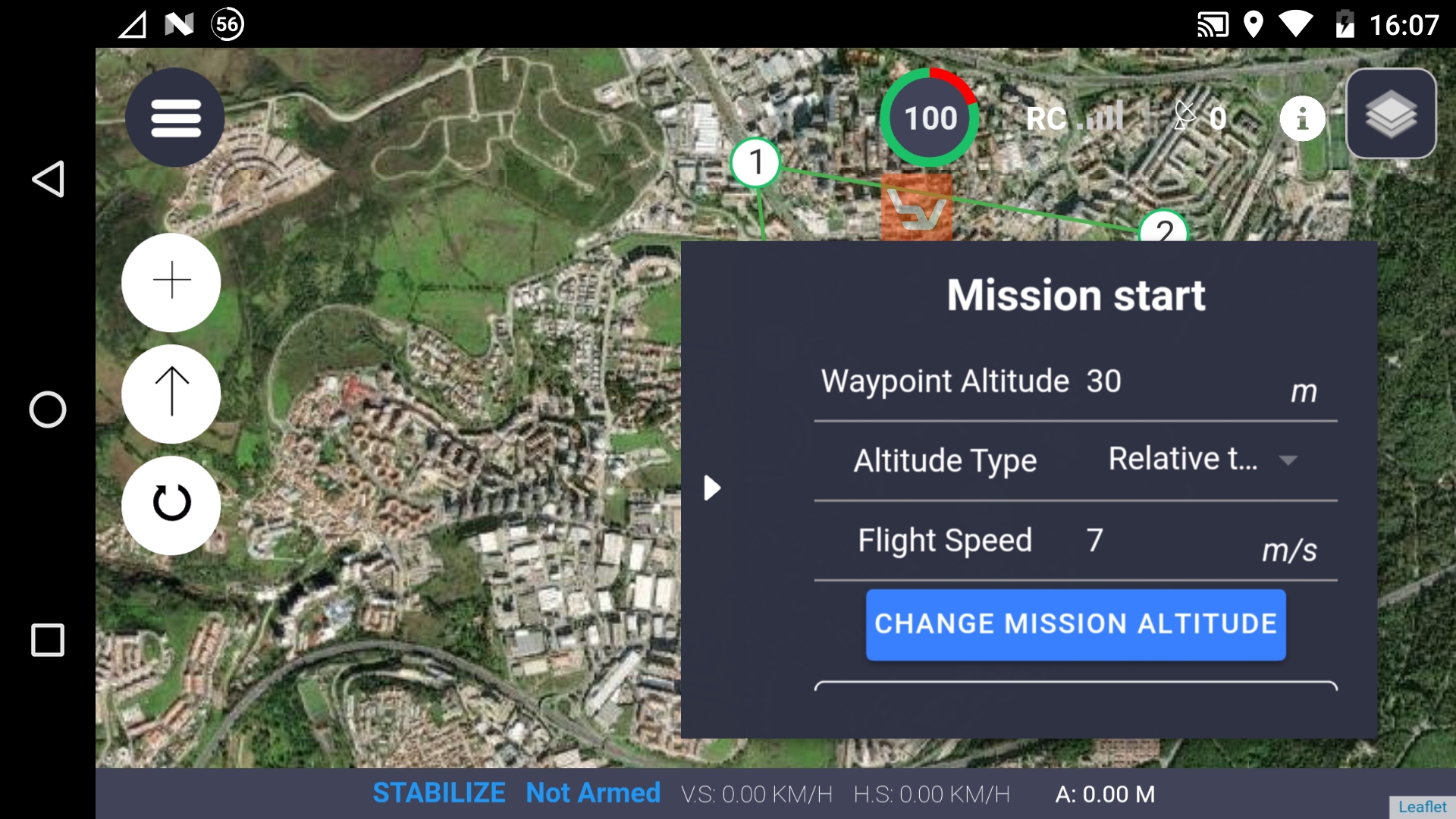
Fig. 16 Mission start screen
Drone Calibration View
If the user selects the calibration view, the following screen will appear. The calibration menu will guide the user through the calibration steps of the drone (please see also section Drone Calibration):
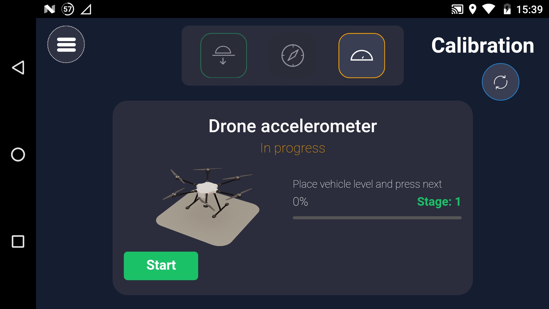
Fig. 17 Calibration view
beXStream® platform
If you purchased a beXStream® platform license, you were given a login to access the application either by using a web browser or by using a Windows/Ubuntu/iOS app.
You can register and access the application by using this login and accessing the web address: https://bexstream.beyond-vision.pt/login.
Please refer to chapter General risks concerning the usage of flying vehicles for further details.