Installation and configuration
This chapter elaborates the procedures for the successful installation and configuration of the beRTK® in the HEIFU® ecosystem. Should you have any doubt, please contact Beyond Vision’s technical support.
beRTK® setup
To prepare the base station to perform well, you should follow the instructions below. You won’t be needing any tools besides the ones that are provided by Beyond Vision base station kit.
Initially, you should charge the batteries (please see section Device Care).
Note
Please be aware that for safety reasons, the batteries are shipped at storage levels. This means that they are at nearly half their capacity and should be charged before their first use.
After charging the batteries, you should insert them in the tray provided for each of them, taking care that there is only one way to insert them.
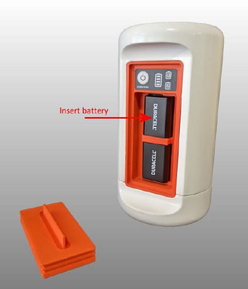
Fig. 93 Battery insertion in the beRTK®
Alternatively, you can connect the external wall adapter to run the beRTK® on mains power, if available. You should use the back power connector for this purpose.
Now, you can turn your beRTK® on and profit from the new acquisition.
If it is the first time you turn the beRTK® on or if you need to adjust any parameter, you should follow the instructions presented in the next section.
beRTK® configuration
In order to be able to configure the RTK base Station you should, after turning it on, connect to the RTKBASE SSID (the default password is: 1123581321) and access the following web site: 192.168.4.1
You should get the screen from the image bellow.
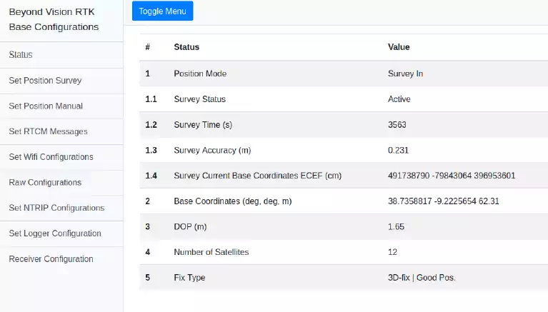
Fig. 94 Home Page
The Web RTK Base Configurations platform allows to do the following interactions with the system: * Check current status * Set the base position
Manually
Survey
Configure Corrections messages output
Connect to a Wi-Fi Network
Allow to send raw configuration commands
NTRIP stream configuration (needs internet connection to be used)
Control the logger
Configure the receiver serial ports and some global system configurations.
Status
The status page presents the following information regarding the GNSS receiver. The fields with (*) are only shown if the Position Mode is [Survey In].
Field |
Values/Description |
|---|---|
|
States if the current position is: [Survey In] [Manual]. Survey In–The Receiver computes its position using the previous ones. Manual – The position was set by the user on the “Set Position Manual” page |
1.1 Survey Status (*) |
States if survey is: [Not Running] or [Running] |
1.2 Survey Time (*) |
Survey duration |
1.3 Survey Accuracy (m)(*) |
Mean survey in 3D standard deviation |
1.4 Survey Current Base Coordinates ECEF (cm) (*) |
Mean Base position ECEF coordinates obtained through Survey In |
|
Current Base coordinates |
|
Current dispersion of position |
|
Number of satellites currently being tracked |
|
|
Set Position Survey
This mode can be useful if the position where the base is going to be set is not known. This combined with a correction stream, allows the user to have a fast and precise base position acquisition. On this mode, the receiver computes its position using a computed mean of previous positions.
The following figure depicts the two parameters of the survey, the survey duration and the desired maximum 3D standard deviation. Only when the two conditions are reached, the position is considered accepted.
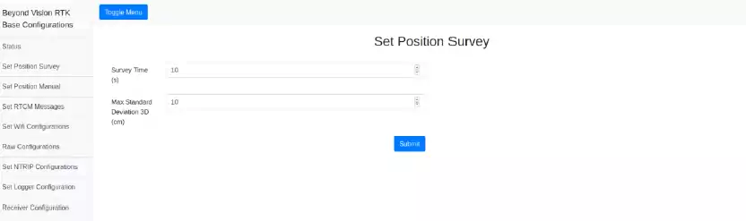
Fig. 95 Set Survey In mode
Manually setting the position
If the user knows the position where the base station is going to be installed, he can set it manually, avoiding the need of waiting for the Survey to be done.
It is possible to set the position on ECEF or LLA referential. The set positions can be accessed on the Saved Positions list.
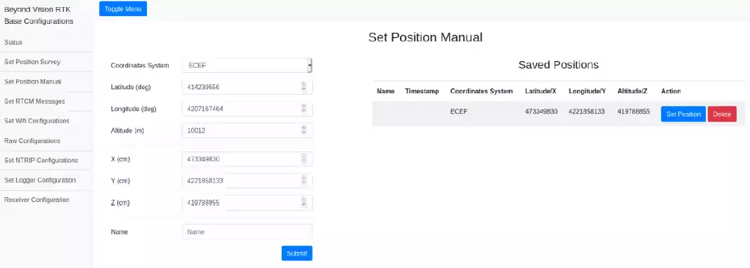
Fig. 96 Page to set the position manually
Set RTCM Messages output
To optimize the amount of data sent through the radio, it is possible to enable/disable the messages and specific output rates. You should input in this field the desired ratio between the navigation rate and the RTCM Messages rate. For example, if the navigation rate is 10Hz, inputting a value of 10 on this field, the RTCM Messages rate will be 10Hz/10 = 1Hz.
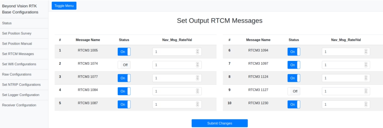
Fig. 97 RTCM Messages configuration window
Set Wi-Fi Configuration
The base can connect to an available Wi-Fi network to allow reception of NTRIP correction data.
This page also provides the current available Wi-Fi SSIDs and, if connected, the base IP on that network.
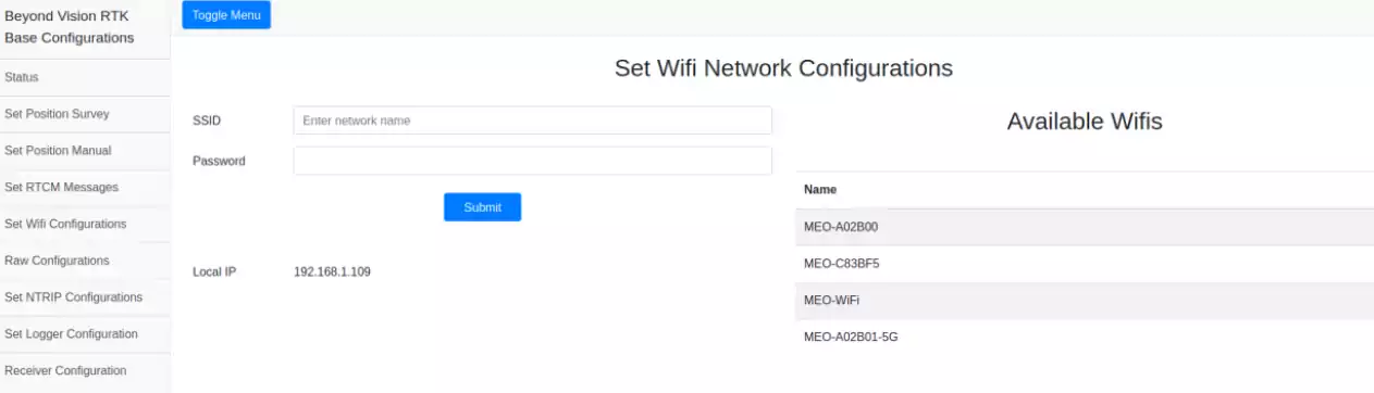
Fig. 98 Setting the Wi-Fi configuration
Raw configurations
This option allows the user to perform advanced configuration of the RTK base chip, the u-Blox F9P. These configurations can be done using the raw syntax of the chip.
You can also send files with multiple commands for multiple configurations.
Warning
The raw configurations interface should only be used by an advanced user.
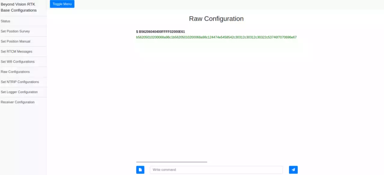
Fig. 99 Raw configuration window
NTRIP stream
The base station provides a wireless link that allows you to connect to an available NTRIP network making it possible to use any NTRIP stream in the area.
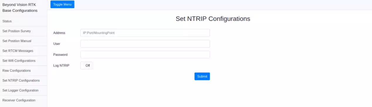
Fig. 100 NTRIP Configuration window
Logger
When it is not possible to use NTRIP streams combined with the survey mode or the base position is unknown and a precise position is needed, the only solution is to log the raw data and then post process it.
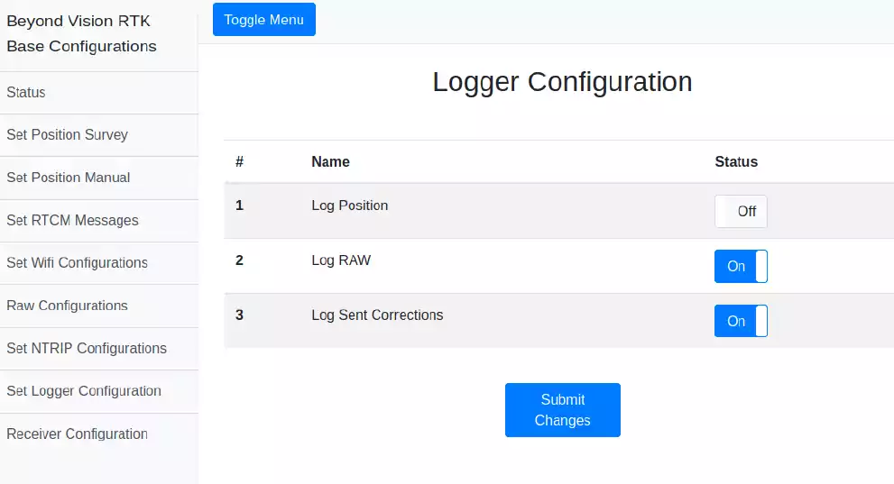
Fig. 101 Logger enabler window
Receiver configuration
This page provides some maintenance configurations, such as the receiver serial port configurations (UART1 and UART2) and rates. Using this window, you can also configure the USB device to use to establish communication with the RTK base chip.
It is also possible to soft power-off and soft reset the base and, if needed, you can do a cold start to the receiver.
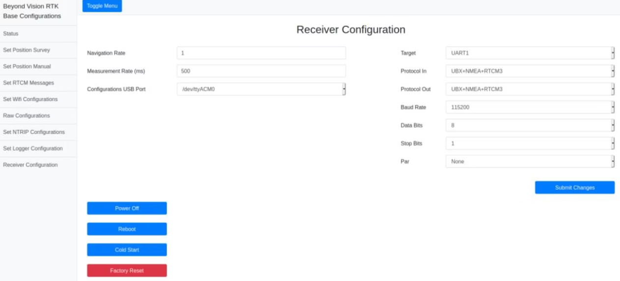
Fig. 102 Receiver Configuration window
You can also do a factory reset to the module. With this option all the configurations you had previously set will be deleted.
beRTK® field deploy
Having your beRTK® ready, you should choose a good place to deploy the device. Please have the guidelines below in mind when choosing the right spot:
Line of sight: It is recommended to choose a place that has line of sight to all the maneuvers that are supposed to be assisted by this base station;
Open field: an open field spot is always a good option to increase the range of the base station broadcast. Elevated areas usually are the best to cover the areas around;
Electromagnetic interference: avoid zones that by its nature are rich in electromagnetic interference (e.g. high voltages cabling, proximity of communications towers, etc.).
Warning
Avoid military areas or civil aviation areas, where the radio emitted by the base station can cause trouble or even be considered illegal.